
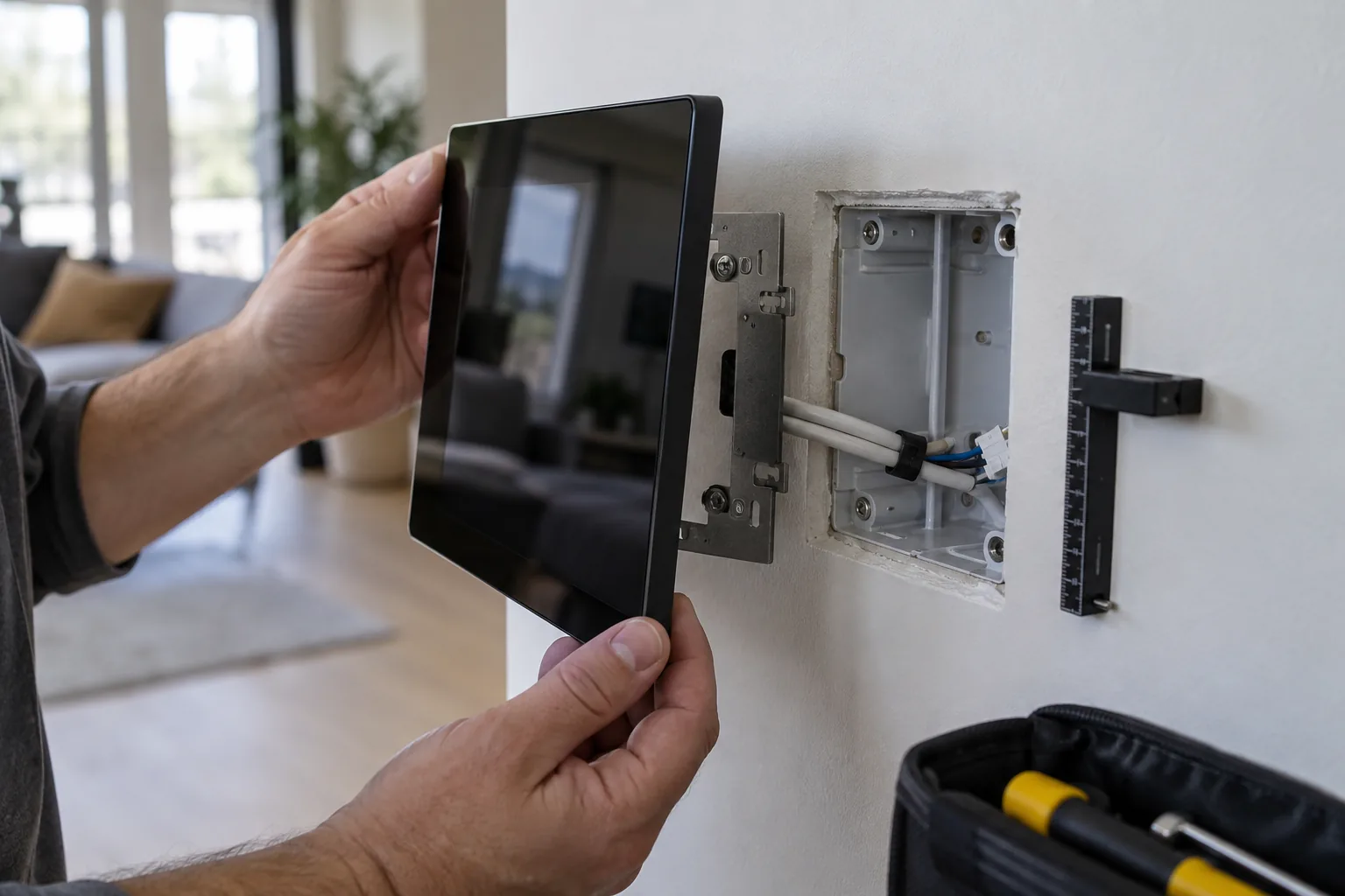
A wall panel can fit the drawing and still refuse to sit flush during installation. The extra depth may be in the Ethernet plug, a stiff cable bend, a screw boss, or the plaster around the box. Pushing harder can load the PCB or trap a cable without resolving the underlying mismatch.
Mechanical planning for a wall-mounted smart control panel should start with a connected assembly inside a representative wall. Treat the back box, bracket, fasteners, cable, heat path, and service movement as product requirements. A clean front rendering does not show most of the space the installer needs.
When evaluating wall-mounted control panels, request rear drawings and mounting instructions alongside the screen and processor specifications.
Identify the actual back boxes
Collect manufacturer drawings and physical samples for the markets being served. Similar face dimensions can conceal different internal depths, mounting threads, screw spacing, and cable-entry positions. Regional names are not a substitute for a controlled drawing.
Record the finished wall surface as the installation datum. A box recessed behind tile or uneven plaster changes how the bracket seats and how screws engage. Include realistic construction variation rather than building the test wall to an ideal CAD plane.
If several boxes must be supported, define the adjustment mechanism and its limits. A slotted bracket can accommodate some offset, but it should not allow a panel to twist under repeated touch or rely on poorly engaged fasteners.
Budget the depth of connected hardware
Start at the visible front surface and work backward: glass, display, PCB, component height, rear shell, connectors, cable bend, and clearance. Include all mating parts. A connector opening in the shell is not the same as space for an installed plug.
| Mechanical item | Information to freeze | Physical check |
|---|---|---|
| Back box | Inner depth, entries, screw positions | Fit actual regional samples |
| Connector | Plug size, latch, exit direction | Insert and remove with gloves if needed |
| Cable | Diameter, minimum bend, stiffness | Route without loading sockets |
| Bracket | Datum, adjustment, screw engagement | Seat on a representative finished wall |
| Rear enclosure | Protrusion, ribs, component clearance | Check assembly tolerances |
| Service access | Removal direction and available slack | Remove without damaging wall or cable |
For an illustrative packaging exercise, a 28 mm rear projection plus a 17 mm cable-routing allowance already needs 45 mm before any additional clearance. Those values are assumptions, not a recommended universal box depth. Use the selected cable’s actual bend requirement and the product’s worst-case dimensions.
Let cables move without moving connectors
Plan strain relief and a service loop that fits inside the box. Too little slack makes removal difficult; too much creates a bundle that presses against the board or obstructs airflow. Check cable behavior at the lowest expected installation temperature if stiffness is relevant.
Avoid placing a connector latch where the installer cannot release it. A screwdriver forced beside a display or PCB can turn routine service into damage. Document the order of disconnecting cables and supporting the panel during removal.
If a product combines low-voltage electronics with other wiring, have the applicable installation and product requirements reviewed by the responsible electrical designer. Mechanical convenience should not determine separation, insulation, or access to energized parts.
Mount through a defined load path
Touch presses, cable forces, and installation torque should transfer through the mounting structure. Review whether a bracket or screw is unintentionally bending the PCB, loading a display edge, or compressing a touch sensor stack.
Specify fasteners, engagement, tightening method, and any controlled torque. Check the material that carries the thread and the number of service cycles expected. Plastic clips that survive the first assembly can still be unsuitable for repeated removal.
During control-panel project planning, agree the visible alignment tolerance. A small rotation may be mechanically harmless but obvious beside a row of light switches. Set a practical installation adjustment rather than relying on the wall opening being perfect.
Follow heat through the installed assembly
Measure power at the workloads the product will actually run: idle dashboard, maximum intended backlight, network activity, audio, video, and any powered accessories. Confirm whether the input power also includes an external load before treating it as heat inside the panel.
Identify the route from processor and power components to a spreader, rear enclosure, front surface, and surrounding air. A metal cover only helps when there is suitable contact and somewhere for the heat to go. Wall insulation and a sealed box can change that route substantially.
Texas Instruments’ thermal metrics guidance explains why package thermal numbers depend on measurement conditions. Do not estimate the finished panel’s processor temperature by applying a datasheet junction-to-ambient value without checking whether its assumptions resemble the assembly.
Run the panel mounted, at the intended orientation and upper ambient condition, until temperatures stabilize. Record component temperature, application performance, throttling, touch behavior, and accessible surface temperature. Approval limits should come from the components, product requirements, and applicable assessment.
Keep antenna and sensor space in the model
A bracket can solve mounting and weaken radio performance at the same time. Review antenna keep-outs, cable routing, metal coatings, and the box material with the wireless designer. Validate signal performance with the panel fully seated.
The panel wireless architecture also affects space: extra radio modules, antennas, and coax connectors need clearance that a front-view drawing cannot show. Avoid assigning the last empty corner to an antenna after the mechanical parts are frozen.
Check microphones, speakers, proximity sensors, and ambient-light sensors as physical systems. Their openings, seals, and placement influence behavior. An internal temperature sensor may measure panel self-heating rather than room temperature unless the design accounts for it.
Test installation and service as repeatable tasks
Build a sample wall using the intended box, wall finish, cable, and power arrangement. Ask an installer to mount and remove the device using the draft instructions. Observe tool access, hand clearance, alignment, cable handling, and the force needed to seat the panel.
Repeat removal and refitting to the agreed service-cycle requirement. Inspect clips, threads, cable jackets, connectors, glass edges, and the wall finish afterward. Keep notes on steps that require improvisation; those are candidates for design changes or clearer instructions.
For custom panel electronics, feed the findings back before final PCB and enclosure release. Rotating a connector or moving a heat source can be inexpensive early and disruptive once tooling and fixtures are approved.
Release an installation package with the product
The mechanical handover should include supported back boxes, dimensioned drawings, fasteners, cable requirements, mounting sequence, thermal configuration, and removal instructions. Link these to the approved hardware revision so later batches remain compatible.
Procurement should compare quotations with those items included. A cheaper panel that requires a different box, an additional bracket, or repeated wall rework can increase the installed cost. Include spare mounting hardware and replacement-unit compatibility in the discussion.
Approve the panel after it fits, operates, dissipates heat, communicates, and can be serviced in the representative wall. That sample gives the project a physical reference for both production quality and installation acceptance.
Frequently Asked Questions
Does matching the back-box face size guarantee fit?
No. Internal depth, screw positions, wall finish, cable entry, connector protrusion, bend radius, and service slack also affect fit. Check actual boxes with the fully connected panel.
Can a metal rear cover solve panel overheating?
It can help when a designed thermal path transfers heat into it and the installation can dissipate that heat. Contact pressure, insulation, antenna placement, and accessible surface temperatures still need review.
When should installation samples be approved?
Before tooling and volume orders, use a representative wall, back box, cables, power source, and application load. Validate fit, fastening, thermal behavior, wireless performance, and repeated service removal.