
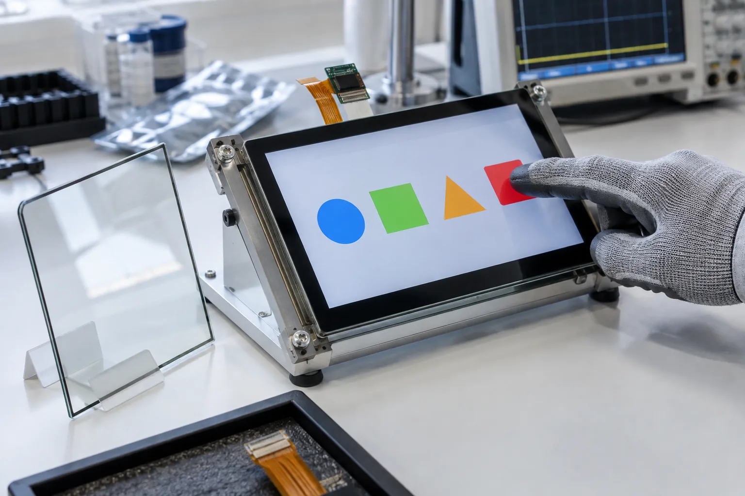
Touch works on the supplier’s open bench, then misses presses near the edge after the glass is fitted into a metal bezel. Another sample responds correctly to bare fingers but becomes unreliable with the operator’s gloves. Both can happen with a perfectly functional Linux or Android driver.
For touchscreen HMI board selection, approve the complete sensing assembly: controller, sensor, cover glass, adhesive, cable, grounding, enclosure, and software configuration. Screen size and an I2C interface are not enough to establish compatibility with the installed product.
An embedded HMI platform should be evaluated with the actual controls users will operate, including the smallest buttons and the most consequential actions.
Define the interaction before specifying the panel
Write down who touches the screen, with what, and under which conditions. Thin disposable gloves, heavy work gloves, a passive stylus, and a bare finger do not produce the same input. Specify the glove material and thickness rather than asking for an undefined “glove mode.”
Describe moisture and cleaning separately. Condensation, droplets, a wet finger, and a film of cleaning liquid are different test cases. Decide whether the required behavior is continued operation or temporary rejection of touch without false activation.
For machinery, identify controls that require a deliberate press or confirmation. The touchscreen and UI must support the product’s control strategy; a display should not be assumed to provide a safety function merely because it presents a stop button.
Freeze the glass and bonding stack
Record cover thickness, material, coating, printed border, adhesive, sensor type, and bonding method. Air gaps and adhesive variation can change the coupling between a finger and the sensor. Mechanical substitutions should therefore trigger touch revalidation even when the display underneath stays the same.
Microchip’s capacitive sensor design guidance explains how cover materials and surrounding conductors affect sensing. Those principles help frame the discussion, but they do not establish a universal thickness limit for a commercial projected-capacitive touchscreen.
Ask the touch supplier to identify the approved stack and the controller configuration used with it. Keep a representative bonded assembly as a reference. A bare sensor sample is a poor comparison when later production units use thick glass and a different adhesive.
Match controller support to the delivered BSP
Confirm the exact controller model, firmware revision, communication interface, interrupt polarity, reset sequence, and supply voltage. Check that the chosen board image supports it, including any firmware-loading or configuration procedure required at boot.
The Android HMI board review should cover coordinate orientation, input-device behavior, wake policy, and application handling. A display rotated to portrait does not guarantee that touch coordinates are rotated correctly with it.
For Linux, verify the driver and input events in the released image. A controller compatible with a vendor demonstration may still need changes in the intended kernel. Document how a replacement controller or firmware update will be qualified rather than accepting an unspecified “equivalent touch IC.”
Treat the cable as part of the circuit
A longer cable adds capacitance and changes exposure to interference. A cable that passes beside a backlight converter or shares a bundle with a switched load can behave differently from the short flex used on the bench.
Freeze cable length, pinout, orientation, connector latch, shield arrangement, and ground return. Review I2C timing and pull-ups for the actual bus if I2C is used; changing resistors without considering the controller’s voltage and current limits can introduce another failure.
Service assembly also matters. The cable needs enough movement for installation without pulling on the connector, and its bend must stay within the cable supplier’s limits. An intermittent latch connection can resemble an electrical-noise problem until the enclosure is opened.
Test noise with the product doing real work
Create a baseline with the approved adapter, enclosure, grounding, and display brightness. Then exercise backlight dimming, Ethernet traffic, radios, storage, relays, and other relevant loads while collecting touch behavior.
| Condition | Observe | Possible next investigation |
|---|---|---|
| Backlight changes | Missed presses or coordinate jumps | PWM coupling, return current, cable routing |
| Different approved supplies | False touches while untouched | Common-mode noise and grounding |
| Gloves and edge targets | Required force and repeatability | Stack, tuning, target size |
| Moisture on glass | Ghost touches or controlled rejection | Water handling and recovery policy |
| Sleep and wake | Delay, lost controller, rotated coordinates | Reset sequence and power state |
| Enclosure fastened | Edge sensitivity or local dead areas | Bezel coupling, stress, cable compression |
These observations narrow the investigation; they are not one-to-one diagnoses. Preserve the original tuning and change a single variable during comparison. Otherwise, a routing fix and a sensitivity change can hide each other’s effects.
Include the actual installation ground arrangement. A setup grounded through a laboratory instrument can appear more stable than a floating field installation. Record the measurement connections so the test can be reproduced.
Use measurable acceptance instead of a quick swipe
A short swipe across the center proves very little about an operator terminal. Create a repeatable grid of targets that includes corners, borders, and controls near the bezel. Define the number of attempts, allowed misses, maximum coordinate error, response timing, and test conditions for the product.
Measure the whole interaction when needed. Touch-controller reporting, Android or Linux event delivery, application load, and screen refresh all contribute to the user’s perceived response. A slow button action is not necessarily a sensor problem.
The HMI integration checklist should connect these results to display, power, and enclosure approval. Record untouched periods as well as deliberate touches; a system with excellent sensitivity can still fail because it activates controls by itself.
Keep tuning under version control
Touch configuration is a production artifact. Record controller firmware, tuning file, checksum where available, sensor revision, and glass stack alongside the system image. Establish whether settings reside in controller flash, the host filesystem, or both.
Do not allow the factory to adjust sensitivity informally until an individual unit passes. That practice can hide bonding variation, poor cable assembly, or a changed component. Investigate the cause and release any new settings through the same approval path as other firmware.
For custom HMI hardware, request service access to controller diagnostics during development. The ability to capture useful data before closing the enclosure can save repeated mechanical disassembly.
Purchase the approved assembly, not a description
The purchase specification should list the panel and controller, glass drawing, bonding materials, cable, approved firmware, tuning version, and representative tests. Define which substitutions need written review and new samples.
During operator-terminal selection, ask who owns the complete touch result. If glass, sensor, board, and application come from different companies, nominate one integration owner and agree how failures will be reproduced.
Approve the sample with its enclosure fastened, its intended supply connected, and the real operator workflow running. That assembly becomes the reference for later lots and for diagnosing a field complaint without guessing which piece changed.
Frequently Asked Questions
Can thicker cover glass be used with any capacitive touchscreen?
No. Glass thickness, dielectric properties, bonding, sensor geometry, controller, and tuning work together. Ask the touch supplier to validate the intended stack rather than extrapolating from a thinner sample.
Does a working touch driver prove that an HMI is ready?
No. Driver operation establishes communication. Glove use, edge accuracy, electrical noise, moisture behavior, sleep recovery, and the final enclosure still require assembly-level tests.
Should sensitivity be increased to solve missed touches?
Only after checking the stack, grounding, cable, and controller data. Increasing sensitivity can also increase false touches, so repeat the false-activation tests after changing tuning.