
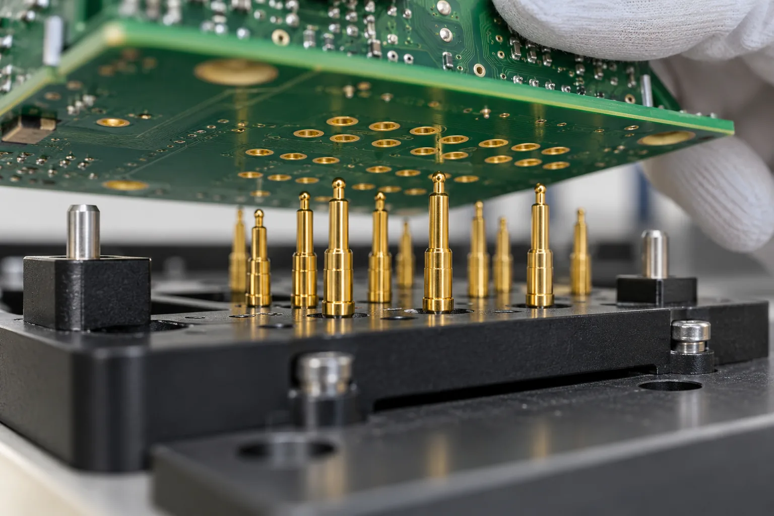
The board passes after the operator opens the fixture and closes it again. Is the product marginal, or did one probe fail to make contact? Without the original measurement and fixture position, the production record cannot answer. It simply says pass.
Reliable fixture contacts depend on target geometry, probe selection, controlled movement, board support, and maintenance. Software can recognize some contact faults, but it cannot compensate indefinitely for a poorly located pad or an overloaded fixture plate. Design the physical interface and the result record together.
For SBC production testing, treat first-pass yield and contact-related retests as separate process signals. A station that eventually passes every board may still be wasting time and concealing defects.
Allocate test targets before layout is frozen
Start from the required measurements and programming operations. Identify which nets need direct access and which can be verified through a functional connector. Place targets with the fixture designer’s spacing, access, and support requirements in mind.
Define the pad size, finish, solder-mask opening, side of access, and keep-out area. Account for nearby components, fixture guide features, and positional tolerances. A pad visible in a layout viewer may be inaccessible after a shield or connector is fitted.
Avoid relying on unapproved alternatives such as touching a tiny component lead because a proper test pad was omitted. The arrangement may work for an engineering sample but be too sensitive to placement variation for repeated production use.
Match the probe tip to the target surface
A flat plated pad, soldered lead, rounded solder deposit, and open via present different contact conditions. Choose tip geometry and material for the actual surface, then verify repeatability and the resulting witness marks.
QA Technology’s probe tip selection guidance explains why target shape and surface condition matter. It also notes that an unsuitable tip can create false failures or damage the unit. Use supplier recommendations as a starting point, followed by tests on representative production targets.
Do not select the sharpest tip by default. Penetrating contamination may improve contact in one application while creating unacceptable pad damage in another. Define acceptable marks and inspect them after the expected number of engagements, including retest and rework.
Calculate force at working travel
Use the probe manufacturer’s specified working travel and force curve. Maximum mechanical travel is not automatically the recommended operating point. The fixture’s tolerance stack must keep the shortest and tallest assembled targets within the approved range.
Add the forces from all compressed probes, then include connector insertion and other loads. As an illustrative calculation, 80 probes operating at 1 N each contribute 80 N before any additional force. That is not a recommended probe force; it shows why many individually small loads can become a significant board load.
Check fixture-plate deflection, closure repeatability, and board support. Place supports where they protect the assembly without contacting prohibited components or creating a new stress concentration. More clamp force is not a sound remedy for a board that is bending between supports.
| Contact feature | Design input | Verification evidence |
|---|---|---|
| Tip and target | Shape, finish, contamination | Repeatable contact and acceptable marks |
| Travel | Probe curve and tolerance stack | Working compression at assembly extremes |
| Board support | Local force and component positions | Controlled deflection during closure |
| Power path | Current, resistance, temperature | Voltage at the unit under load |
| Signal path | Bandwidth and return arrangement | Required signal quality through fixture |
| Maintenance | Wear mechanism and usage | Inspection and replacement records |
Make locating independent of electrical contact
Use suitable mechanical features to establish board position before probes reach their targets. Probe tips should not be responsible for dragging a misplaced board into alignment. Review guide-pin engagement, loading direction, and the possibility of inserting the wrong variant.
The functional fixture layout should show reference datums and allowed tolerances. If production panels are separated before test, include depanelization variation and edge condition in the review.
Make the operator’s loading action repeatable. A nest that accepts two orientations but damages the board in one of them needs a design change, not just a larger warning label. Verify that the closure mechanism cannot reach its testing position with a visibly misloaded unit.
Measure the power path under load
A continuity check at low current does not prove that a fixture contact can supply a booting SBC. Contact resistance, cable resistance, and current sharing can lower the voltage at the unit during startup.
Measure at the board-side test points while the intended load runs. Where measurement accuracy warrants it, use separate force and sense connections with an appropriate instrument. Also check whether parallel power probes share current as intended rather than assuming equal sharing.
Document safe sequencing and discharge. Establish the intended contact order where the design requires it, and prevent a powered fixture from leaving an uncontrolled condition during loading or removal. Qualification should include the failure of a contact that carries an important return or enable signal.
Give fast signals a suitable test path
Long unshielded fixture wiring and arbitrary probe returns can distort a high-speed signal. A pogo contact is not electrically invisible. Decide whether the purpose is a low-speed functional check, a programming connection, or a demanding signal-integrity measurement.
For USB, Ethernet, or other high-speed interfaces, use an appropriate connector or controlled fixture path when required. Keep the test boundary explicit: a loopback before the shipped connector may miss defects in that connector or its downstream components.
Discuss these constraints during custom board development. Moving a target or adding a ground contact while layout is open is usually easier than trying to correct an unstable fixture after the PCB is released.
Record the contact problem before retrying
Log unit identity, fixture ID, nest position, test step, measured value, limit revision, attempt number, and any operator reseating action. Keep the first result even when a later attempt passes.
Correlate failures by location. The same symptom across many boards in one nest points toward a different investigation from the same board failing in several verified stations. Neither pattern alone proves the cause, but both are more informative than an overall yield percentage.
The factory test automation should distinguish product failure, contact or fixture error, aborted test, and infrastructure error. Use controlled retries with a defined purpose. Repeating a measurement until it falls inside limits can turn a marginal connection into a false pass.
Release a maintenance process with the fixture
Define inspection and cleaning using the probe supplier’s approved methods. Abrasive or improvised cleaning can change the tip and leave debris. Set replacement criteria from wear observations, contact performance, and usage rather than assuming every probe has the same life.
Keep spare parts, drawings, wiring records, and an approved reference unit. After maintenance, verify both repeatability and defect detection using appropriate known-good and known-fault conditions. A station that reliably passes the reference unit but misses a deliberately broken path is not ready.
The final acceptance package should let another technician restore the fixture and reproduce its results. Include the contact map, working travel, loading instructions, limits, maintenance history, and example failures. That makes the fixture a controlled production tool instead of a mechanism that only its original builder knows how to keep running.
Frequently Asked Questions
Will a stronger pogo-pin spring fix intermittent contact?
Not necessarily. Check alignment, target finish, contamination, probe travel, and board support first. Extra force can damage pads or bend the board while leaving the actual contact problem unresolved.
Can one probe specification cover every test point?
Only where the target geometry, current, signal requirements, travel, and surface conditions are compatible. Power, fine-pitch signal, and high-speed paths may require different contact arrangements.
How can quality teams distinguish fixture faults from board defects?
Retain first failures and every retest, correlate them with fixture position and contact ID, and compare reference units and known fault samples. A pass after reseating is useful evidence, not a reason to erase the first failure.