
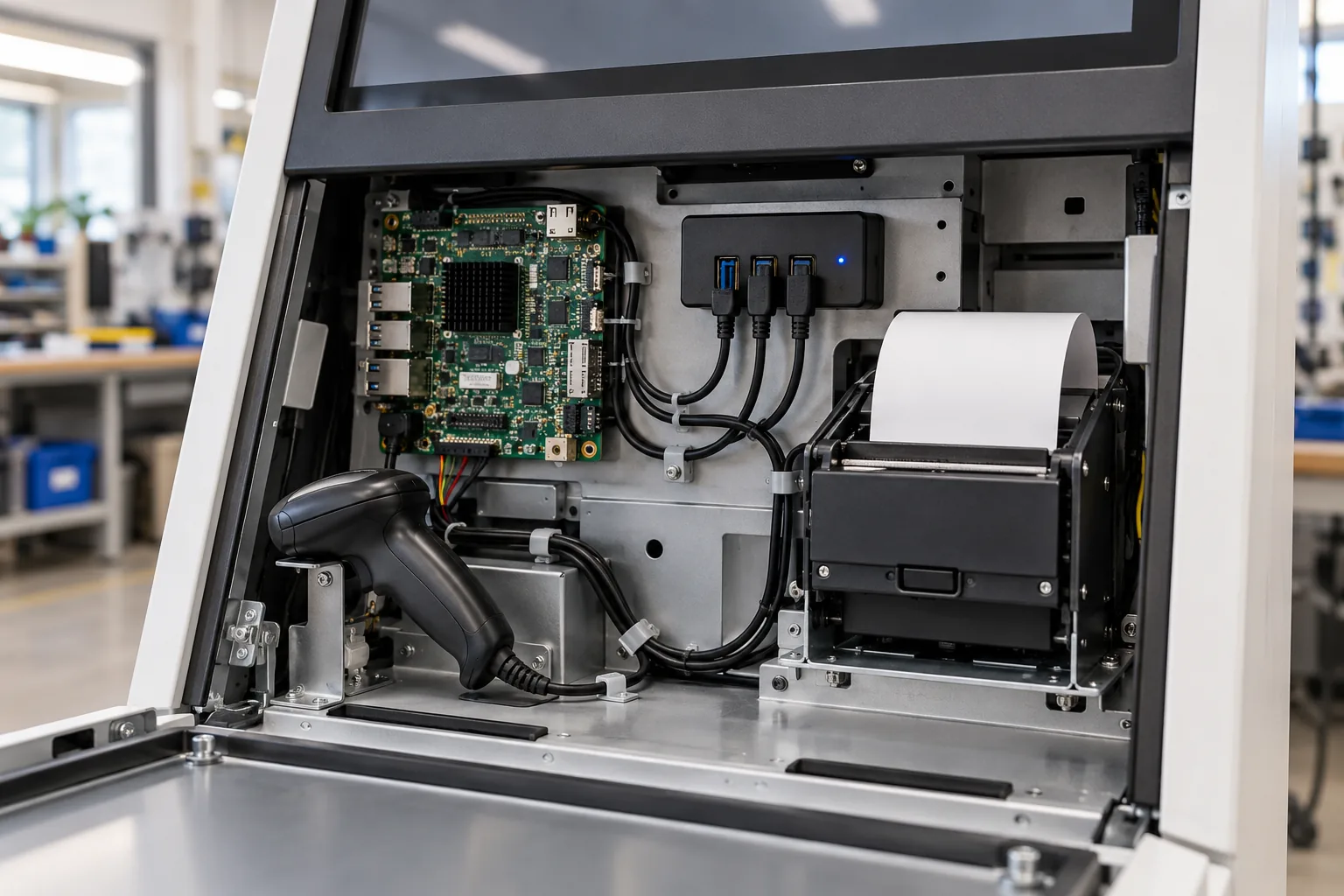
A barcode scanner, camera, and receipt printer each work when connected alone. The integrated kiosk then loses the scanner whenever the printer starts, or opens the wrong camera after a reboot. The problem is no longer whether the SBC has USB support. It is how the complete set of devices shares power, bandwidth, identity, and recovery.
For self-service terminal board design, approve a USB architecture with the actual accessories attached. Count the devices, but also draw their connection paths and failure boundaries. An extra socket is useful only when the product can power it, identify it, operate it, and recover it predictably.
Draw the topology behind the connectors
Map each accessory to its root controller, intermediate hub, port, cable, and power source. Two external sockets may share the same upstream path. An internal camera can compete with a service connector even when they are on opposite sides of the enclosure.
For self-service terminal hardware, ask for this topology during board evaluation. Include internally connected touch, audio, wireless, and storage devices where applicable. Hidden consumers matter when diagnosing a shared failure.
Record USB speed and transfer requirements rather than using connector color as the specification. The mating cable, hub, endpoint, and negotiated link determine what the path actually supports.
Build the power budget from operating states
List idle, active, startup, and fault behavior for each peripheral. A scanner’s illumination, a camera’s operating mode, and a printer’s separate power supply may have very different effects. Do not assume every accessory draws its main operating power from USB.
Calculate the shared supply demand, then measure it at the relevant connectors. Include conversion losses, cable drop, hub consumption, and the board’s own load. A sufficiently rated adapter does not prove that a narrow trace or individual port switch can carry the required current.
Use simultaneous events when testing: cold start with all devices attached, camera activation while scanning, or printing while the display is at its approved brightness. Choose cases from the real workflow rather than summing unrelated maximum figures without understanding when they occur.
| Accessory or function | Record before integration | Test that exposes shared problems |
|---|---|---|
| Barcode scanner | Interface mode and illumination demand | Repeated scans during other activity |
| Camera | Format, resolution, frame rate, bandwidth | Continuous capture with other traffic |
| Receipt printer | Separate supply and status behavior | Print while scanning and reconnecting |
| Touch controller | Upstream path and wake behavior | Interaction during device resets |
| Hub | Supply, port switching, fault reporting | Startup and controlled port faults |
| Service port | Allowed devices and access policy | Approved service operation under load |
Choose hub features for the recovery plan
A hub can offer individual or grouped port-power control, different overcurrent reporting arrangements, and configuration options. Confirm the hardware implementation, not only the controller’s feature list. Grouped power switching may reset several accessories when only one needs attention.
The TI USB hub reference specifications show examples of per-port or ganged power control and overcurrent inputs. Those capabilities illustrate what to ask about; they do not make a particular hub suitable without reviewing the complete circuit and software support.
Decide how the application or service software can request recovery and observe its result. A switch controlled only by an undocumented manufacturing command is not yet a usable field-maintenance feature.
Prevent unintended power paths
Examine the case where the SBC is off but an accessory or externally powered hub remains on. Check the design for back-power through VBUS or other connections, and use the relevant controller and switch specifications to define the allowed states.
Sequence power and data as required by the selected devices. A peripheral that starts slowly may not be ready when the application first enumerates available hardware. Repeatedly rebooting the mainboard to find it is not a substitute for a defined readiness timeout and recovery policy.
Measure startup at the accessory end of the cable as well as at the supply. If a fault appears only after installation, the extra cable resistance or connector transition may matter more than the adapter’s headline wattage.
Do not use enumeration order as identity
Two identical USB serial devices can exchange names after reconnecting. A camera index may also change when another device appears first. The application needs a stable identification method, not an assumption based on yesterday’s startup order.
Where supported, use trustworthy serial identifiers or a documented physical-port mapping. Check whether the selected accessory actually provides a unique serial number; some models do not. Record product variants and interface modes so procurement substitutions cannot silently change discovery behavior.
The terminal peripheral integration requirements should include permissions and application reopening after removal. Successful enumeration in the operating system does not mean the app regained access to the right endpoint.
Share bandwidth deliberately
A camera streaming continuously is different from a scanner sending a short code. Evaluate the combined data path using the required formats and timing. A nominal bus rate is not all available application payload, and adding hubs does not create independent upstream bandwidth.
Keep latency-sensitive or high-throughput devices on appropriate paths when the board offers them. Test the workload rather than choosing a topology from theoretical maximums alone. Include the compressed or uncompressed video mode actually used by the application.
For a custom terminal mainboard, interface allocation can be changed before layout. Give the board team the accessory workload and recovery requirements early; moving a camera to another controller later may require more than rerouting one connector.
Recover the transaction, not just the USB link
After a disconnect, the application must close stale handles, rediscover the correct device, restore its configuration, and decide what happened to the interrupted operation. A recovered USB connection is only part of that sequence.
Printing is a useful example. If acknowledgement is lost after a receipt starts, a blind resend can create a duplicate. Define how device status and application records determine whether to resume, retry, ask for assistance, or report an incomplete operation.
Use bounded retries and targeted resets. Preserve the reason for recovery, the affected device, and its last known state. Avoid resetting a shared hub while an unrelated critical operation is active unless the product’s recovery policy explicitly permits it.
Validate cables and installation handling
Use the approved cable length, routing, retention, and connector transitions in the test unit. A short development cable sitting outside the enclosure does not represent a production harness bent around a printer mechanism.
Secure cables so routine paper loading and service movement do not pull on the board sockets. Check that connectors can be reseated without removing unrelated components. Label the internal connections sufficiently to prevent a service replacement from moving a device to the wrong physical port.
During terminal factory validation, test the customer-facing path and retain useful identifiers in the record. Confirm that a shipping configuration, not an engineer’s temporary port mapping, is installed.
Approve the complete terminal after simultaneous workload, removal, reconnect, power sequencing, and application recovery tests pass. Keep the accessory models, firmware, cables, hub configuration, and software build with that result. The next purchasing substitution should be checked against this package, not against the fact that both devices happen to use USB.
Frequently Asked Questions
Does a powered USB hub remove the need for a kiosk power budget?
No. Its supply, switches, wiring, connectors, and port configuration must support the attached devices and startup behavior. Also account for accessories with separate power inputs and prevent unintended back-power paths.
Can all terminal peripherals share one USB hub?
Sometimes, but bandwidth, timing, power, and failure impact must be checked together. A camera or problematic accessory may justify a separate path so its behavior does not disrupt essential devices.
Is resetting a USB device always safe during a transaction?
No. The application must know whether an action completed before retrying it. A reset during printing or another stateful operation can lose status or duplicate work unless recovery is designed explicitly.