
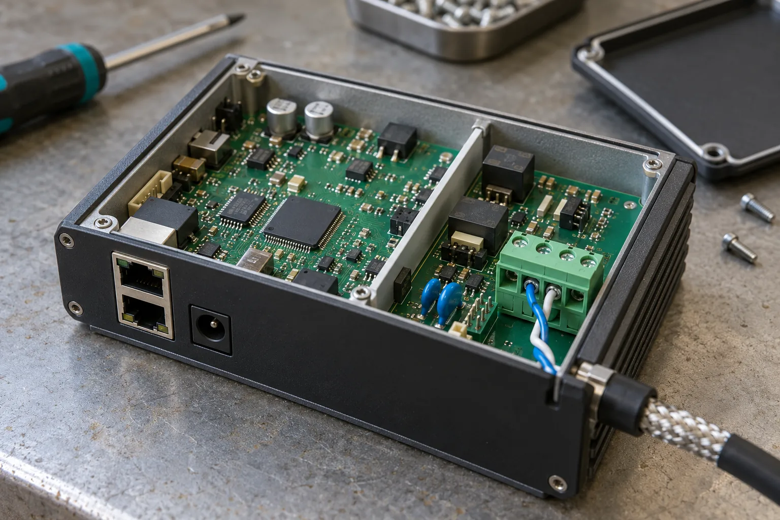
Two meters respond correctly on a short bench cable. After the gateway reaches a cabinet with several branches and separately powered devices, readings become intermittent. Increasing the timeout makes the dashboard look quieter, but it does not explain whether the fault is wiring, transmitter timing, or a slow instrument.
RS485 gateway design should separate three jobs: making the electrical bus reliable, implementing the protocol correctly, and recovering without corrupting application data. Establish evidence for each job. A working UART and a Modbus library are useful starting points, not a complete field interface.
For an industrial gateway board, ask for the circuit assumptions and tested bus configuration alongside the supported baud rates.
Begin with a bus drawing, not a port count
List the devices, cable route, branch lengths, power sources, and grounding arrangement. Identify whether the gateway sits at an end of the trunk or between other nodes. That position affects termination and installation instructions, even when the PCB stays unchanged.
Confirm two-wire half-duplex versus four-wire operation. Document signal polarity by function and manufacturer pinout rather than trusting A/B labels alone; equipment vendors do not always label those terminals consistently. Include the reference conductor and shield treatment in the drawing.
Texas Instruments’ RS485 design guidance explains bus topology, termination, loading, and fail-safe considerations. Use those principles to review the actual installation rather than treating a maximum cable-length headline as a guarantee at every speed.
Specify what the isolated boundary must separate
Isolation is a system decision. Determine which equipment may sit at different ground potentials and what disturbance or safety requirement the interface must address. The answer affects the transceiver, isolated supply, PCB spacing, and connector-side protection.
Trace every path across the proposed boundary. A shared ground connection, debug lead, shield termination, or non-isolated power rail can change its behavior. During measurement, a grounded oscilloscope connection can also alter the circuit being tested; use suitable instruments and procedures.
Do not describe a port as providing a particular safety isolation rating merely because one component has that rating. The assembled design and its assessment establish the claim. Procurement should request the documented port specification and applicable evidence, not just an isolated-transceiver part number.
Keep termination and bias understandable to installers
For a conventional terminated half-duplex trunk, the two cable ends need the intended termination. Intermediate nodes should not silently add another parallel resistor. Choose how an installer enables it: switch, jumper, or a controlled assembly option.
Biasing and termination serve different purposes. Biasing establishes an idle state when no driver is active; termination controls reflections. Receiver fail-safe behavior also varies by transceiver. Review the complete loading and noise margin rather than copying resistor values from a board with a different node count or supply.
Make the shipped state unambiguous. A service technician should be able to determine the port configuration without removing the mainboard or reading an undocumented GPIO value. Preserve that setting through an image update if software controls it.
| Decision | Record in the design package | Verify on the assembled product |
|---|---|---|
| Bus position | End node or intermediate node | Correct termination state |
| Polarity | Connector pins and signal meaning | Known device communicates as wired |
| Isolation | Complete electrical boundary | No unintended return connection |
| Idle behavior | Bias network and receiver behavior | Stable receive state with idle bus |
| Direction control | UART/driver support and timing | Full request and response captured |
| Recovery | Retry limits and stale-data policy | Missing device does not stall the bus |
Watch the last transmitted byte
On a half-duplex port, the gateway must release its driver after the final byte has actually left the UART. Returning from a write call does not necessarily mean that transmission is complete. Releasing too early can truncate a frame; releasing too late can collide with a fast response.
Prefer hardware or kernel-supported direction control where it meets the requirements. If the design depends on application-timed GPIO switching, verify it under CPU load and scheduling delays. Capture transmit data, driver enable, and the response together so a timeout can be traced to a physical event.
The Linux gateway platform evaluation should include the exact UART driver and BSP revision. An RS485 configuration option exposed by Linux does not prove that every timing feature is implemented by that controller driver.
Budget Modbus timing and polling separately
Modbus RTU framing uses defined silent intervals; application response timeout is a separate setting. At lower baud rates, character time makes a noticeable contribution. Higher-rate implementations also need to follow the serial-line specification’s timing recommendations rather than applying an arbitrary delay everywhere.
For example, with an 11-bit character format at 9,600 baud, one character takes about 1.15 ms. An eight-byte request already occupies about 9.17 ms on the wire, before the response, required gaps, processing, or retries. This is a timing illustration, not a throughput promise.
During gateway protocol planning, estimate the complete polling cycle. Separate fast control observations from slow diagnostics. One absent instrument should not consume enough repeated timeout windows to make all remaining readings useless.
Specify whether writes may be retried. Repeating a read is usually easier to reason about than repeating a command whose first response was lost. The application must understand the device’s command semantics instead of assuming every timeout means nothing happened.
Preserve the meaning of missing data
A gateway that republishes yesterday’s value without a quality flag can look healthy to the cloud while the field link is broken. Record the last successful acquisition time and distinguish fresh, stale, unavailable, and invalid data in the application contract.
Keep useful counters: successful transactions, CRC failures, timeouts, exception responses, and reconnect or reset events. An exception response is evidence of a responding device with an application-level issue, not the same condition as silence on the bus.
Bound recovery actions. Resetting a whole gateway whenever one meter stops answering can interrupt unrelated channels and erase the evidence needed to diagnose the original failure.
Test through the connector, then introduce faults
Factory tests should reach the actual external RS485 path, including transceiver and connector. An internal UART loopback bypasses important assembly faults. Use a controlled external peer and record both the configured communication parameters and the result.
Qualification should go further: representative cable and node loading, separately powered devices, repeated power sequences, a disconnected node, incorrect settings, and agreed disturbance tests. Record the expected outcome for each case before testing. Survival, continued communication, and automatic recovery are different requirements.
For a custom RS485 board, agree test points and fixture access before layout release. Keep production screening practical, while retaining the more extensive qualification evidence for the approved design.
Hand over the installation assumptions
Include the pinout, cable recommendation, topology limits, termination method, bias arrangement, grounding notes, serial settings, and troubleshooting counters in the release package. Identify which changes require a new review, including a transceiver substitution or UART driver update.
The gateway deployment checks should reproduce the intended wiring rather than only repeating bench communication. Approve the port when engineering can explain a failed transaction and support can restore service without guessing which resistor or timeout to change.
Frequently Asked Questions
Does every RS485 node need a termination resistor?
No. For a conventional terminated two-wire bus, termination belongs at the two physical ends, with values matched to the cable. Adding termination at every node increases loading. Confirm the actual topology and transceiver requirements.
Is an isolated RS485 transceiver enough to isolate a gateway port?
Not by itself. Power, ground, protection, shield connections, PCB spacing, and other attached interfaces must preserve the intended boundary. Review the complete circuit and its specified isolation performance.
Can a successful Modbus read approve the production gateway?
It proves one transaction under one condition. Approval also needs direction timing, multiple devices, missing responses, power sequencing, wiring faults, recovery, and tests through the actual external connector.