
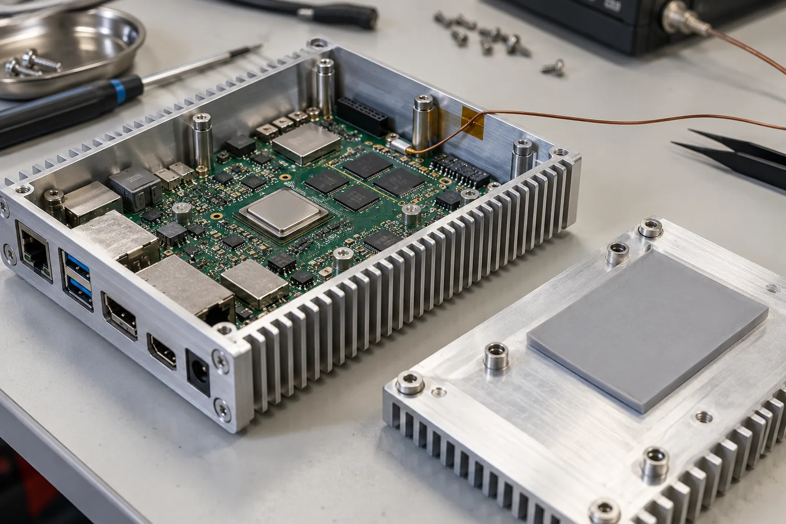
A five-minute demonstration can make a passively cooled board look faster than the finished product will be. The enclosure warms gradually, frequency limits change, and the application settles at a different throughput. For an unattended terminal or gateway, that sustained result matters more than the first benchmark score.
Rockchip SBC thermal design should connect workload, power, heat transfer, mechanical tolerances, and the production software policy. Choose cooling against the installed product and its operating environment. There is no single heatsink recommendation that covers every Rockchip board, enclosure, and application.
Define the workload that must remain useful
List concurrent tasks: UI rendering, video decoding, camera processing, NPU inference where used, networking, storage writes, and attached peripherals. Establish the required output rate, latency, or response time rather than specifying only CPU utilization.
For a Rockchip SBC platform, test the application and BSP combination being considered for production. Different accelerated paths can change which blocks do the work and where power is consumed. A CPU stress tool is useful for one purpose, but may not reproduce a media or inference workload.
Separate peak and sustained requirements. A brief response burst may be acceptable at a higher power level, while continuous processing needs a stable thermal path. State how long each operating mode can last and what happens when several modes overlap.
Draw the path from silicon to the room
Heat may pass through a package, interface material, spreader, enclosure, and surrounding air. Identify the important contact areas and the bottlenecks. A large metal enclosure does little for a processor that has no effective contact with it.
Compare open-bench and installed conditions. Orientation, wall proximity, cabinet airflow, dust, neighboring equipment, and enclosure sealing all affect heat rejection. If a fan is used, include its control, obstruction, lifetime, and service requirements instead of treating airflow as permanently available.
Keep power components, storage, radios, and other devices in the review. The hottest or least tolerant component may not be the processor. An enclosure modification that improves one contact can also block airflow around another part.
Select the thermal interface from the tolerance stack
Measure the gap at assembly extremes, not only nominal CAD dimensions. Include PCB position, component height, standoffs, enclosure flatness, and screw engagement. Choose a pad with suitable thickness, conductivity, compression behavior, and electrical characteristics for that gap.
The simple bulk-material relation is useful for understanding a tradeoff:
thermal_resistance = thickness / (conductivity * contact_area)
For an illustrative 1 mm pad with conductivity 3 W/(m*K) over a 20 mm by 20 mm area, the bulk resistance is about 0.83 K/W. Actual contact resistances, compression, spreading, and the rest of the heat path are not included. This is not a prediction of the installed chip temperature.
More thickness can help bridge a gap but is not free thermal improvement. Excessive compression can bend the PCB or load components. Agree the installation method and inspect contact evidence on representative assemblies.
Read sensors by identity, not by index
On Linux images exposing the standard thermal interface, inspect zone names before interpreting values. Zone numbering can vary across kernels and board descriptions. A value from thermal_zone0 is not automatically the CPU temperature.
The Linux kernel’s thermal interface documentation describes zone types, temperatures, trip points, and cooling-device integration. Check the vendor implementation and available sensors on the released BSP.
This read-only inventory can be used where those files exist and are readable:
for zone in /sys/class/thermal/thermal_zone*; do
  [ -r "$zone/type" ] && [ -r "$zone/temp" ] || continue
  printf '%s: ' "$(cat "$zone/type")"
  cat "$zone/temp"
done
Standard temperature values use millidegrees Celsius. Keep the zone name, timestamp, workload, and image version with readings. Package sensors do not replace measurements on other components or accessible enclosure surfaces.
Evaluate throttling alongside application output
Record temperature, available frequency information, input power, and the application’s useful output over time. A clock reduction can be a deliberate protective action. The product question is whether required performance remains available at the specified environment.
Do not disable thermal protection to produce a more attractive score. Test the policy that will ship. Changing limits or cooling maps requires review and validation, not a hidden adjustment in a demonstration image.
During RK3566 and RK3576 selection, compare sustained performance within the proposed enclosure. A more capable processor may offer useful headroom, but its name alone does not establish the cooling requirement or the final throughput.
| Test condition | What to record | Decision it supports |
|---|---|---|
| Idle product | Background load and input power | Unexpected heat sources |
| Sustained application | Throughput, latency, temperatures | Continuous service capability |
| Peak combined workload | Transient power and response | Short-burst behavior |
| Upper ambient | Stabilized temperatures and output | Environmental margin |
| Cooling fault where applicable | Protective response and recovery | Fan or airflow failure handling |
| Assembly variation | Contact and thermal spread | Production tolerance robustness |
Make the test long enough to answer the question
Run until the relevant temperatures and application output have stabilized under the agreed condition. A fixed duration chosen without observing the thermal response may end before the enclosure reaches its meaningful operating state.
Record ambient temperature near the installation, supply conditions, orientation, enclosure revision, accessories, software image, and workload configuration. Repeat the important cases after cold start and after a warm restart if they produce different behavior.
Use suitable measurement methods. Thermocouple attachment can affect contact and temperature; infrared readings depend on surface properties and setup. Keep those details with the report so another engineer can understand why two measurements differ.
Translate the approved assembly into factory checks
Specify pad part number, dimensions, location, protective-film removal, fasteners, and assembly sequence. Make it possible to detect a missing pad or an incorrectly seated spreader without dismantling every finished unit.
A short production thermal-response check can help identify gross assembly problems if it is validated against known defects and normal variation. It does not replace full design qualification. Establish what the check can actually detect before treating a temperature threshold as proof of correct assembly.
For custom Rockchip hardware, reserve mechanical support and contact geometry early. The Rockchip customization scope should include the cooling assembly and validation responsibility, not only the bare PCB and BSP.
Keep the result useful after component changes
Archive the approved workload, raw temperature and performance traces, assembly drawings, thermal materials, and software policy. Identify changes that trigger retesting: enclosure finish, pad supplier, processor configuration, memory or power component, firmware policy, or application workload.
Purchasing needs this boundary because a seemingly equivalent thermal pad or enclosure can alter the result. Support needs it because an overheating report may come from a changed installation rather than the original board design.
The release decision should state the environment, sustained capability, permitted cooling arrangement, and protective behavior. Those are actionable product limits. A photograph of a heatsink and a maximum-frequency specification are not.
Frequently Asked Questions
Is the CPU temperature enough to approve SBC cooling?
No. Check other heat-sensitive components, accessible surfaces, enclosure conditions, and sustained application performance. A cool processor does not prove that the PMIC, storage, radio, or connector remains within its limits.
Does a thicker thermal pad improve cooling?
Not automatically. It may bridge a mechanical gap but increases bulk thermal resistance at the same material conductivity and area. Select thickness and compression using the tolerance stack and pad supplier's data.
Should thermal throttling be disabled during performance testing?
No. Evaluate the production thermal policy and record sustained throughput. Removing protection can invalidate the test and risk damage. If the application misses its target, improve cooling or revise the workload and platform requirements.