
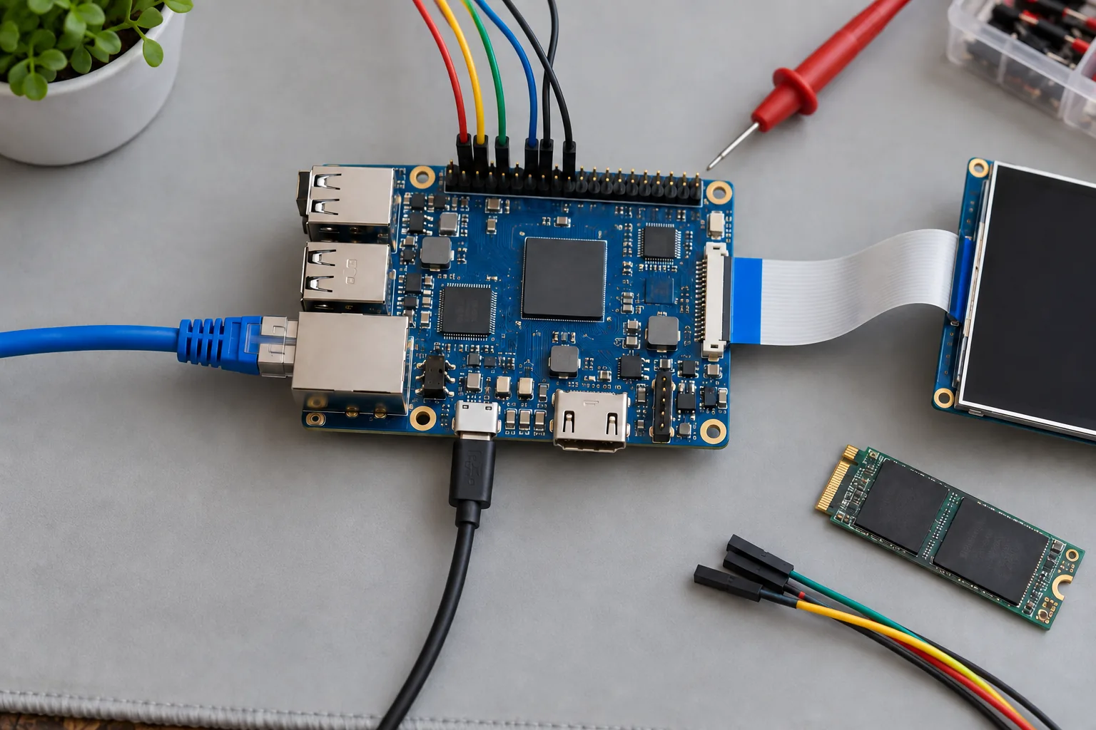
An Ethernet interface that appears in Linux but never holds a link can send a team toward cable swaps and driver patches. The cause may be simpler: the production PCB uses a different PHY reset pin from the reference board, while the image still loads the reference device tree.
Device tree planning starts with a mapping between the released schematic and the software description. For an embedded Linux SBC, the useful deliverable is a reviewed set of sources, a known compiled DTB, and evidence that the bootloader loads the intended configuration on each hardware revision.
Establish which files control this board
Identify the exact kernel tree, configuration, compiler, bootloader, and board DTS. Vendor BSPs can differ substantially from upstream Linux, including binding names and driver behavior. A configuration copied from a newer kernel may compile while remaining unsuitable for the kernel shipped in the product.
Record the included DTSI files and overlays. Shared files should describe genuinely shared hardware; board-specific connectors and peripheral choices need a clear owner. When adapting a Linux SBC, request the source used to build the supplied image rather than an unrelated example from an SDK folder.
Trace the bootloader’s DTB selection. A correct source change has no effect if a stale file in the boot partition, a FIT image, or a different boot path supplies the running tree. Include that selection mechanism in release notes.
Create a hardware-to-software map
Use the schematic revision as the starting reference. List each peripheral, its bus address, interrupt, reset, supplies, clock, pin group, and expected Linux driver. This exercise exposes missing dependencies before engineers begin enabling nodes by trial and error.
| Interface | Hardware facts to capture | First runtime evidence |
|---|---|---|
| Ethernet | PHY address, reset, clock, interface timing | PHY detection and sustained traffic |
| UART | Connector mapping, voltage, flow control | Known data received at the intended port |
| GPIO | Polarity, pull, voltage domain, owner | Expected level through reset and operation |
| Display | Panel, bridge, supply, backlight, endpoints | Stable image through sleep and resume |
| Storage | Bus width, supplies, voltage switching | Detection and repeatable I/O under load |
Keep connector labels in this map even when they do not appear as device tree properties. Application and factory teams need to know which external port corresponds to a Linux device. A technically correct driver name does not tell an operator which socket to test.
Resolve pin ownership before debugging peripherals
Check each multiplexed pad against every enabled function. A UART, PWM output, and GPIO may share possible pads, but they cannot independently own the same physical signal at the same time. Reference-board pin groups are especially easy to retain after connector changes.
Review default and sleep states with hardware engineers. Define the safe state of relay enables, transceiver direction, backlight control, and power switches during boot and suspend. Device tree settings do not necessarily control the earliest reset interval, so include bootloader behavior and physical pull resistors in the review.
For custom Linux hardware, this review belongs before layout release. It can prevent a PCB assignment that forces avoidable software work or creates an unsafe output pulse before Linux starts.
Ethernet: follow the complete clock and reset path
Identify the MAC-to-PHY interface and establish who supplies each clock. Confirm PHY address straps, reset polarity, supply enable, and reset timing against the actual component. A driver probing successfully proves only part of that chain.
For RGMII, document where clock delays are introduced: MAC, PHY, or board routing. The selected mode and driver properties must match the physical timing arrangement. Copying a delay setting from another board can create intermittent errors that only appear at a particular link speed or temperature.
Test cold boot, warm reboot, cable removal, link renegotiation, and sustained bidirectional traffic. Keep link-error counters and hardware revision with the results. Avoid calling Ethernet complete after a single ping.
UART and GPIO: make the signal meanings explicit
A UART node describes the SoC controller; an external RS485 connector also depends on its transceiver, direction control, termination, and wiring. Verify that the driver supports the required RS485 behavior and that any device tree options are valid for that driver version.
Reserve the debug console deliberately. If an application uses a port that also emits boot messages, those messages can reach attached equipment. Remove unintended console use across the bootloader and kernel only after retaining a reliable recovery route.
For GPIO, use the binding’s polarity semantics and distinguish logical active state from measured voltage. Identify lines owned by kernel drivers before allowing userspace access. GPIO controller numbering can change; application interfaces should avoid depending on accidental enumeration order.
The Linux peripheral adaptation scope should include these electrical and application boundaries, alongside the DTS changes themselves.
Display and storage depend on power sequencing
A display path can involve a controller, bridge, panel, backlight, and several supplies. Review endpoint connections, reset order, timing, and brightness control together. A visible boot logo does not establish that Linux’s display configuration will survive a mode change or resume cycle.
Storage deserves the same attention. Match bus width, removable status, supply rails, and supported signaling modes to the board. Do not enable a faster timing mode merely because it appears in a reference DTS. The controller, storage component, voltage arrangement, routing, and driver all need to support it.
Exercise the selected storage mode with read/write workloads and repeated resets. Keep destructive write tests off irreplaceable production data. Record whether failures are configuration errors, electrical margin problems, or storage faults before changing several properties at once.
Validate descriptions and test the hardware separately
The Linux kernel’s device tree binding documentation explains schema validation with dt_binding_check and dtbs_check. Run the checks supported by the actual kernel tree and resolve relevant warnings before treating the configuration as a release candidate.
For a configured ARM64 kernel source tree with the required cross-toolchain and schema dependencies, the commands are typically:
make ARCH=arm64 CROSS_COMPILE=aarch64-linux-gnu- dt_binding_check
make ARCH=arm64 CROSS_COMPILE=aarch64-linux-gnu- dtbs_check
These are build-host commands, not commands for an installed gateway. Legacy vendor kernels may lack these targets or complete schemas; document that limitation and use their available build checks without claiming equivalent coverage.
Keep a runtime test matrix beside the build results. Test interactions too: Ethernet traffic while storage writes, display resume with touch active, and serial traffic during CPU load. Shared clocks, pins, and power dependencies can make individually passing interfaces fail together.
Release the DTB with its hardware compatibility record
Bundle the kernel configuration, DTS sources, DTB checksum, overlay order, bootloader selection notes, and supported PCB revisions. Include the peripheral part numbers used for approval. Substituting a PHY, touch controller, or storage device must trigger a review of that record.
Agree the handover during BSP integration planning. The supplier should identify what can be rebuilt, what is delivered as a binary, and which tests need repeating after a kernel update.
Close the work with a short reproducibility check: start from the released sources, rebuild the configuration, install it through the documented path, and repeat the essential peripheral tests. That gives the next engineer a dependable starting point when the hardware changes again.
Frequently Asked Questions
Can a device tree fix a missing Linux driver?
No. A device tree describes hardware and its connections. A matching driver must exist and be enabled in the kernel, and any required firmware must also be available.
Should every PCB revision have a different DTB?
Use a different configuration when hardware changes affect the description, such as pin assignments, regulators, PHYs, or displays. Record compatibility explicitly even when multiple revisions can share a DTB.
Does passing dtbs_check prove that the board works?
No. Schema checks find description errors covered by the bindings. Electrical timing, actual wiring, supply behavior, and peripheral operation still require testing on the target hardware.