
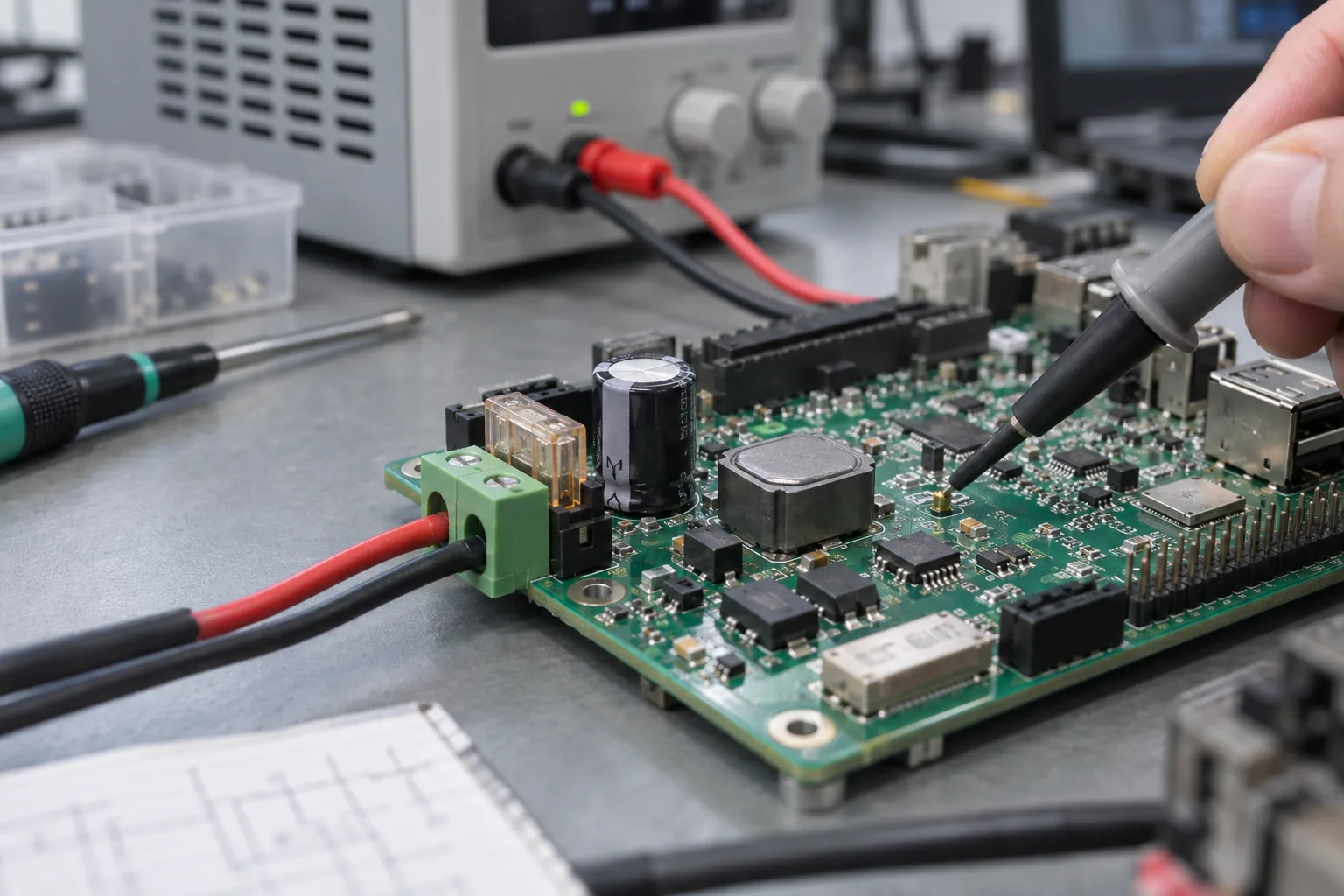
A board runs for days from a laboratory supply, then reboots whenever a nearby contactor operates in the customer cabinet. Increasing the adapter wattage may change nothing. The disturbance could be a brief voltage dip, a common return path, input ringing, or a peripheral load appearing during startup.
Industrial SBC power input design needs an operating envelope: continuous voltage limits, load behavior, abnormal conditions, and the response expected from the complete product. “12V” and “24V” describe nominal rails. They do not specify what the board must tolerate at its connector.
Before selecting an industrial SBC, obtain the board-level input specification and test it against the installation, including its supply, wiring, enclosure, and attached loads.
Write the electrical conditions at the connector
Separate normal operation from survival conditions. A board might be required to run through a defined low-voltage interval but only survive a different transient without damage. Those are distinct acceptance criteria and may call for different circuitry.
Capture supply tolerance, cable length and gauge, connector resistance, expected polarity errors, switching loads, ambient temperature, and grounding. For a battery-powered installation, include charging voltage and discharge behavior. For a cabinet supply, include startup with other loads connected to the same rail.
| Input condition | Requirement to define | Evidence to collect |
|---|---|---|
| Continuous supply | Minimum and maximum at the board | Operation across voltage and load |
| Startup | Rise rate and simultaneous peripherals | Current waveform and boot result |
| Voltage dip | Depth, duration, and required response | Rail capture and recovery log |
| Miswiring | Applicable polarity and fault cases | Protection behavior and inspection |
| Transient disturbance | Test method, level, coupling, source | Recorded waveform and functional result |
| Hot enclosure | Ambient and cooling assumptions | Component temperature under load |
Use agreed application test conditions. There is no universal industrial disturbance level that can be inferred from a nominal voltage alone.
Calculate demand at the lowest operating voltage
Add processor, display, storage, radios, external USB devices, and interface loads. Separate continuous demand from short events such as backlight startup or cellular transmission. Power quoted for a bare board may exclude most of the finished product.
An illustrative calculation for a converter supplying 15 W at 90% efficiency from a 9 V input is:
input_current = output_power / (efficiency * input_voltage)
              = 15 W / (0.90 * 9 V)
              = 1.85 A approximately
These are example assumptions, not a board rating. Startup peaks and design margin still need measurement. As input voltage falls, a regulated load can draw more input current, increasing cable drop and pushing the board closer to undervoltage shutdown.
Check connectors, copper, fuses, protection devices, and converter limits against that low-voltage case. Also measure the supply at the board rather than trusting the number displayed at the power source.
Coordinate the protection stages
A useful power-path review follows current from connector to load: current limiting, reverse-polarity handling, surge clamping, filtering, conversion, and downstream supervision. Their order and component choices depend on the circuit; a generic block diagram is not a finished design.
Texas Instruments’ 24V protection reference design demonstrates several separate protection functions, including current, voltage, and polarity faults. Its tested implementation is useful background, but its ratings cannot be transferred to a different SBC layout or installation.
A TVS must clamp the expected disturbance below downstream limits under the actual surge current. Its standoff voltage also needs to accommodate normal supply operation. Coordinate it with upstream current protection so a sustained abnormal supply does not simply overheat the clamp.
Likewise, an input filter may interact with a cable and a switching converter. Check startup and ringing with the intended source impedance. Adding capacitance can change both filtering and inrush behavior.
Inrush can look like a software boot loop
A current-limited supply may repeatedly start and collapse while charging the board’s input capacitors. Linux never gets far enough to log the event. Watch the input and main rails from the first application of power, using a suitable measurement setup.
If startup fails only with a display, modem, or storage device attached, measure the combined sequence. Staggering loads or controlling their enable signals may reduce the peak, but the chosen method must still meet the product’s startup requirement.
During industrial interface planning, allocate peripheral power explicitly. A USB connector and a 5 V rail do not automatically establish the available current or protection behavior for an external accessory.
Define what happens below the operating range
Undervoltage lockout should lead to a predictable state. Review reset thresholds, hysteresis, rail discharge, and the conditions that permit another boot attempt. A slow supply ramp can be more revealing than a clean on/off switch.
Decide whether the product must ride through a short interruption, shut down gracefully, or reset and recover. Graceful shutdown requires early detection and enough energy for the measured workload. A capacitor chosen by intuition is not evidence that databases and storage will finish their writes.
For abrupt loss, validate storage consistency, application recovery, and external outputs. A controller that returns with stale relay commands can create a different problem from one that simply needs extra boot time. Record the intended output states before reset, during restart, and after application initialization.
Include grounding and enclosure heat
Review return currents from display backlights, radio transmitters, relays, and external cables. An input supply can remain within limits while a shared ground path disturbs serial communication or touch sensing. Protective earth, chassis, shield, and signal ground need deliberate treatment within the product architecture.
Power loss becomes heat in regulators, protection MOSFETs, connectors, and inductors. Evaluate them at both voltage extremes in the installed enclosure. The processor may stay cool while a power-path component reaches its limit.
A custom industrial mainboard can place the power entry, protection, and thermal contact around the installation. Give the designer cable exit and enclosure drawings early enough to use that freedom.
Build a test sequence that isolates causes
Begin with steady voltage and controlled load, then add startup, hot plug, voltage ramps, and agreed disturbance tests. Change one variable at a time. Record hardware revision, firmware, supply settings, cable, peripherals, ambient, and measurement points.
Run the application during testing and watch its outputs. Survival without permanent damage, uninterrupted operation, and automatic recovery are different outcomes; the report should say which one occurred.
In the production acceptance checklist, distinguish design qualification from checks performed on every board. A line test can verify input current and startup at selected points. It does not replace full surge or temperature qualification.
Before approving the purchase specification, require a tested input range, documented protection scope, known load allowance, and a recovery result. Those four items help purchasing distinguish a board suitable for the cabinet from one that merely boots on the bench.
Frequently Asked Questions
Can a 12V SBC connect directly to a 24V supply?
Only if the board's documented operating input range includes the actual 24V supply conditions. A connector that fits and a regulator's absolute maximum rating do not establish board-level compatibility.
Does a TVS diode provide complete industrial input protection?
No. Surge clamping must be coordinated with source impedance, current protection, voltage ratings, thermal limits, and the expected disturbance. Reverse polarity and sustained overvoltage require their own review.
Should a brownout always trigger a graceful Linux shutdown?
Only when detection and stored energy provide enough verified time. Otherwise, design predictable reset and recovery, protect persistent data, and validate abrupt power removal.