
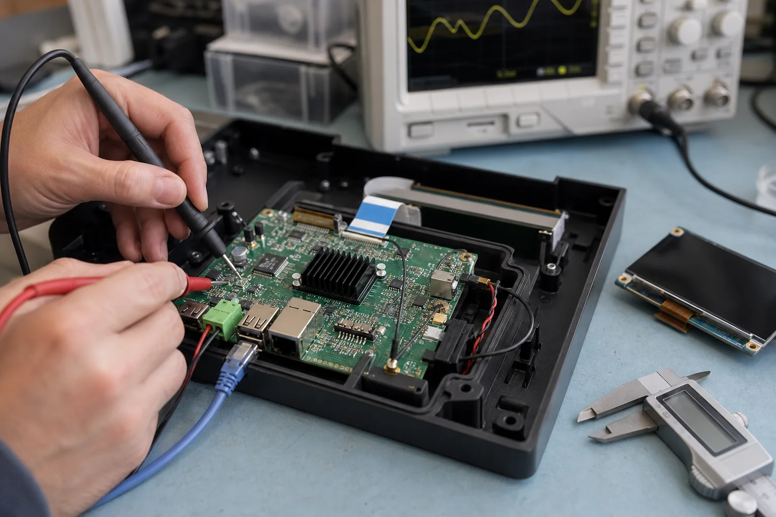
A standard SBC can prove an application quickly. Trouble usually starts when the same board is pushed into a finished product: ports face the wrong wall, cables cross the display, the power input lacks field protection, the antenna sits behind metal, or half the connectors remain unused. At that point, customization is less about adding features and more about removing compromises.
Building a custom SBC means turning a working platform into repeatable product hardware. The job connects electronics, enclosure design, Android or Linux software, component supply, factory testing, and service requirements. If one of those areas is left until the first prototype, the board may boot and still be unsuitable for production.
The practical starting point for custom SBC development is a short list of constraints that cannot move. Everything else should remain a supplier proposal until the tradeoffs are understood.
Decide how much customization is actually needed
Not every product needs a new processor board. Choose the lightest approach that removes the product’s real constraints.
| Customization path | Typical changes | Where it fits |
|---|---|---|
| Standard SBC configuration | Memory, storage, image, cables, heatsink | Software proof, low volume, open enclosure |
| Adapter or carrier board | Power, terminal blocks, field I/O, connector routing | Stable compute module, moderate mechanical change |
| Modified reference SBC | Outline, connectors, display, wireless, selected circuits | Proven SoC and BSP with product-specific hardware |
| Fully custom SBC | SoC, memory, PMIC, I/O, mechanics, test access | Fixed requirements, volume, cost or supply control |
This decision affects NRE, sample time, unit cost, board height, BSP risk, and long-term sourcing. An adapter can be the right answer for a 100-unit industrial tool. The same stack of boards and cables may be expensive and unreliable in a 10,000-unit wall terminal.
Write a product baseline before drawing the board
Start with the installed device. Record the screen and touch part numbers, external peripherals, network roles, input voltage, restart behavior, mounting method, ambient temperature, cable lengths, target boot time, and expected operating life. Add prototype, pilot, annual, and lifetime quantities; one quantity alone does not describe the purchasing problem.
Separate every requirement into four labels:
- Fixed: changing it would affect the product, customer approval, or tooling.
- Preferred: useful, but open to a justified alternative.
- Supplier selection: the result matters more than the chosen part.
- Future option: reserve only when the business case is credible.
That last category deserves restraint. A spare camera, cellular, or battery interface can add routing, protection, software, test time, and cost even if it is never populated.
Freeze the enclosure and connector geometry early
Board outline, mounting datums, connector openings, component height, antenna keep-out, heat-transfer area, and cable bend radius should be reviewed together. A PDF is useful for discussion; native 3D enclosure files are better for collision checks.
Keep service and production access in the model. Technicians may need the debug UART, recovery key, storage socket, or status LED after assembly. Factory fixtures need test pads that remain reachable with the final mechanical parts fitted. An enclosure-first layout review helps prevent an electrically correct board from becoming an awkward assembly.
Select hardware and BSP as one system
Processor selection should follow workload and interfaces, not a benchmark table. Define display resolution, video and camera use, memory pressure, storage writes, application load, thermal limits, boot target, and hardware interfaces. Then check whether a mature reference design and software release cover the required peripherals.
For an Android SBC platform, validate display timing, touch, GPU/video paths, audio routing, Wi-Fi and Bluetooth, USB permissions, launcher behavior, app startup, recovery, and OTA expectations. For a Linux SBC platform, confirm kernel baseline, device tree, drivers, services, watchdog, storage layout, network recovery, update strategy, and access to logs.
A component described as “supported” may only exist in a vendor demo. Ask what was tested on the selected kernel or Android release, whether source or binaries are supplied, and who owns regression testing after an SDK update.
Review the electrical design around real loads
The schematic should reflect actual peripherals and cables. USB current, display backlight surge, relay or motor noise, camera startup, cellular transmit peaks, and hot-plug events can expose a weak power design that looks fine in a static calculation.
Review these areas explicitly:
- DC input range, reverse protection, surge, brownout, and grounding
- PMIC sequencing, reset, boot straps, clocks, and recovery mode
- DDR, storage, Ethernet, USB, display, camera, and audio interfaces
- Protection and isolation on cables that leave the enclosure
- Wireless module supply, antenna position, coexistence, and certification scope
- Debug, programming, current measurement, and fixture test points
The official IPC standards resources provide useful manufacturing context. They do not replace a project-specific schematic, layout, signal-integrity, power, DFM, and test review.
Define prototype acceptance before samples arrive
An EVT sample should arrive with a test matrix, not a vague request to “check whether it works.” Name the board revision, software image, display, cables, peripheral models, supply, and test duration. Record failures against the same requirement IDs used during design.
| Validation area | Evidence worth keeping |
|---|---|
| Power and boot | Rail measurements, startup cases, brownout recovery, boot log |
| Interfaces | Port, peripheral, cable, image version, duration, result |
| Display and touch | Timing, brightness, sleep/wake, touch accuracy, noise cases |
| Thermal | Ambient, enclosure state, workload, temperature, throttling |
| Reliability | Power cycles, network recovery, storage stress, watchdog action |
The first board revision rarely answers every product question. Use EVT validation gates to separate hardware bring-up from enclosure validation and factory-process approval. A change should have an owner, reason, affected files, and retest scope.
Design production into the board
Mass production needs more than a flashable image. Decide how serial numbers and MAC addresses are allocated, how firmware versions are recorded, which functions are tested on every unit, and what evidence follows each lot. Place fixture pads before layout release; adding them after EVT often creates avoidable routing work.
The production package should identify the approved BOM, allowed alternates, PCBA revision, system image, application version, flashing tool, fixture version, work instruction, label data, packaging, and known limitations. When a component changes, the team should know whether it requires purchasing approval, BSP regression, RF checks, or a full pilot run.
Keep responsibilities visible
The customer normally owns product behavior, enclosure decisions, application acceptance, target markets, and commercial forecast. The board supplier owns the agreed hardware, BSP adaptation, prototype evidence, and manufacturing controls. Display, wireless, cloud, app, and certification partners may own additional pieces.
Write those boundaries into the project scope. Otherwise, phrases such as “support the camera” or “provide OTA” can mean a driver to one team and a finished user workflow to another.
Final recommendation
Customize an SBC only after the product constraints are clearer than the development-board conveniences. Choose the smallest customization path that solves enclosure, I/O, power, software, cost, supply, and factory problems. Then keep one requirements baseline across hardware, BSP, mechanics, validation, and production. That discipline is what turns a custom PCB into maintainable product hardware.
Frequently Asked Questions
What is the first step when customizing an SBC?
Start with the installed product rather than the PCB. Freeze the enclosure limits, display, interfaces, power behavior, operating system, application workload, production quantity, and acceptance tests before selecting the customization path.
Can an existing SBC design be modified instead of starting from zero?
Often, yes. A proven reference board can provide the processor, memory, PMIC, and BSP baseline while the custom design changes the outline, connectors, display path, wireless module, power input, or field I/O. The reusable scope must be confirmed before quoting.
How long does custom SBC development take?
The schedule depends on customization depth, component availability, enclosure readiness, BSP changes, prototype revisions, certification, and pilot production. A connector-level revision is much shorter than a new SoC, DDR, PMIC, and BSP design.
When is a custom SBC ready for mass production?
It is ready after the approved hardware revision, production software image, enclosure assembly, thermal behavior, interfaces, recovery cases, factory flashing, functional fixture, traceability, and pilot-run yield have all been validated.
Frequently Asked Questions
What is the first step when customizing an SBC?
Start with the installed product rather than the PCB. Freeze the enclosure limits, display, interfaces, power behavior, operating system, application workload, production quantity, and acceptance tests before selecting the customization path.
Can an existing SBC design be modified instead of starting from zero?
Often, yes. A proven reference board can provide the processor, memory, PMIC, and BSP baseline while the custom design changes the outline, connectors, display path, wireless module, power input, or field I/O. The reusable scope must be confirmed before quoting.
How long does custom SBC development take?
The schedule depends on customization depth, component availability, enclosure readiness, BSP changes, prototype revisions, certification, and pilot production. A connector-level revision is much shorter than a new SoC, DDR, PMIC, and BSP design.
When is a custom SBC ready for mass production?
It is ready after the approved hardware revision, production software image, enclosure assembly, thermal behavior, interfaces, recovery cases, factory flashing, functional fixture, traceability, and pilot-run yield have all been validated.