
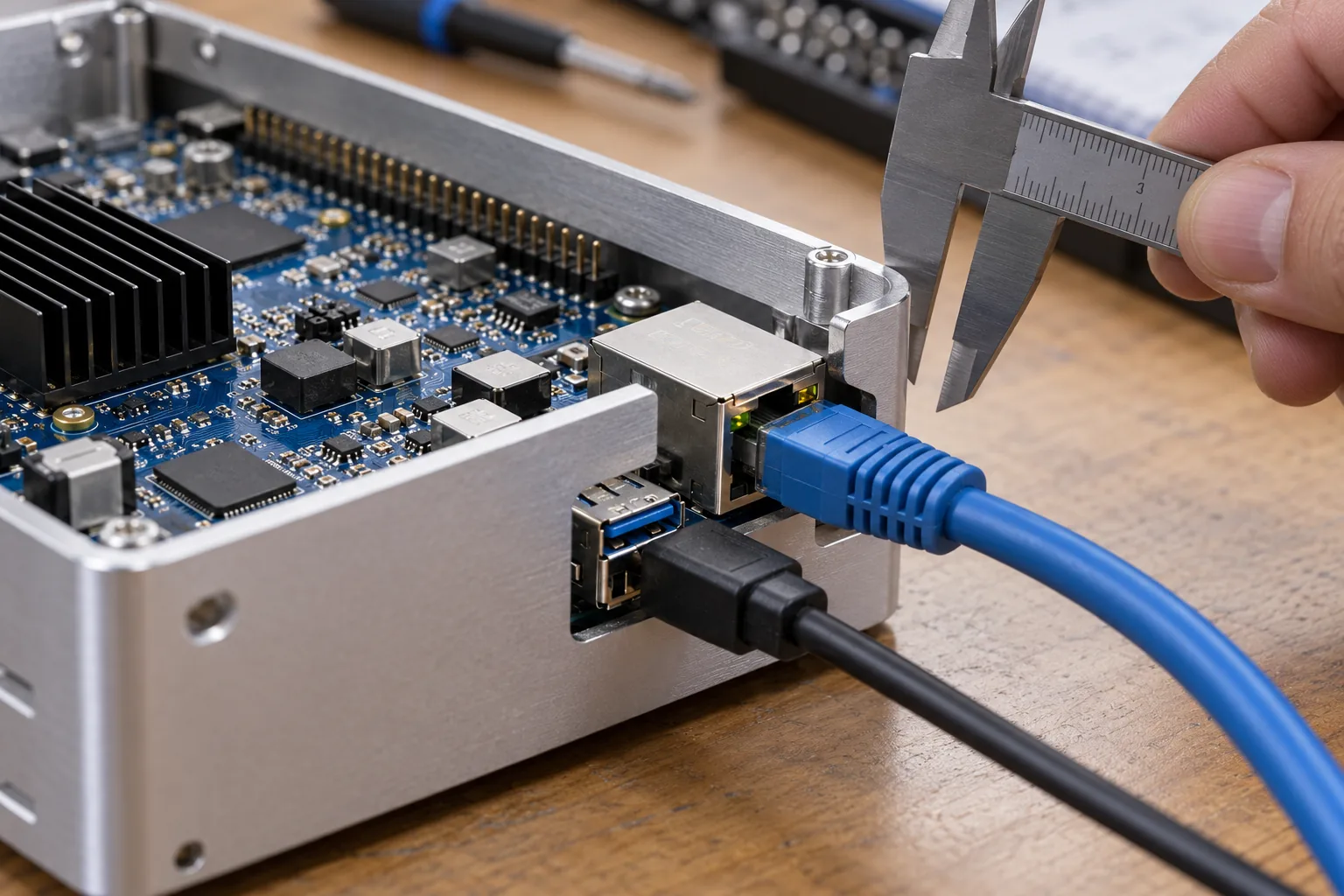
An Ethernet jack fits neatly against the enclosure wall in CAD. The production cable arrives with a longer boot, and the plug can no longer turn inside the product. The board outline was correct; the missing part of the design was everything that mates with it.
Custom SBC connector planning starts with connected hardware, not isolated footprints. Approve the connector, mating half, cable, retention, insertion path, and service movement together. Those choices influence board area, enclosure tooling, assembly time, test access, and the cost of a field replacement.
For a custom SBC design, freeze the interface arrangement early enough that the hardware and mechanical teams can still move a port without forcing a major redesign.
Describe the interface in physical terms
Create a connector schedule with one row per port. Record signal function, connector part number, mating part, pin assignment, cable type, current requirement, and the person who owns each decision. Include internal display, touch, speaker, battery, debug, and antenna connections, not only customer-facing sockets.
Then add how the connection is used. A cable fitted once at the factory has different handling requirements from a service port opened every month. A connector accessible only after removing the display carries a different repair cost from one behind a service cover.
Define the enclosure coordinate system and the mating direction. Terms such as “right-angle connector” can be ambiguous across drawings; show the cable exit and the installed orientation explicitly.
Check the entire insertion and removal path
Place the real mating plug in the mechanical model. Include its boot, latch, strain relief, cable diameter, and minimum permitted bend. Check the hand or tool movement needed to insert it, verify engagement, release the latch, and withdraw it.
A static clearance model can miss a latch that needs to lift or a plug that must approach at an angle. Build a simple enclosure sample and perform the assembly sequence before approving expensive tooling. The person fitting the cable should not need to flex the board to make the connection.
For example, a panel-mounted socket may fit within the allocated width while its service cable blocks a neighboring screw. That is an assembly-order constraint. Either move the hardware or document and validate an order that remains practical during repair.
Treat alignment as a tolerance problem
Board fabrication, component placement, connector geometry, standoffs, and enclosure cutouts all contribute variation. Identify the functional datum and calculate the stack where fit matters. Nominal dimensions lining up on a screen do not demonstrate that production extremes will mate.
Samtec’s connector alignment guidance highlights the difficulty of simultaneously mating multiple board-to-board connectors. Check the manufacturer’s allowable misalignment; do not assume two rigid connector pairs will absorb the PCB and mounting tolerances between them.
Where appropriate, consider a single connector, a cable connection, or a connector family with controlled float. Each option changes cost and packaging. Choose the solution using the actual tolerance budget, rather than adding extra mounting force until the prototype fits.
| Review item | Required input | Typical late discovery |
|---|---|---|
| Mating envelope | Plug and cable drawings | Cable boot hits the cover |
| Retention | Latch travel and access | Plug seats but cannot be removed |
| Alignment | Connector and assembly tolerances | Two mating pairs bind together |
| Load path | Cable pull and support arrangement | Socket load bends the mainboard |
| Service life | Expected mating cycles | Factory handling consumes connector life |
| Procurement | Approved mating pair and tooling | Substitute cable reverses pin order |
Keep cable forces out of fragile parts
Review where insertion force and external cable pull go. A surface-mount socket with small solder anchors should not automatically become the mechanical restraint for a heavy harness. Enclosure support, cable clamps, or a separately mounted connector may be needed.
Do not place strain relief where it merely transfers the load to another vulnerable component. Check the complete path from cable to chassis or mounting structure. During PCBA mechanical review, examine board deflection around the connector and nearby components.
Flexible flat cables need their own handling plan. Confirm contact orientation, stiffener position, insertion depth, bend restrictions, and lock type. A cable that can be inserted backwards or incompletely deserves an assembly check, not just a warning buried in a drawing.
Validate electrical ratings in the installed arrangement
Pin count and pitch do not establish usable current. Review contact ratings, wire gauge, number of loaded contacts, temperature rise, ambient conditions, and the supplier’s derating assumptions. Power contacts may need particular attention during startup or accessory peaks.
For high-speed interfaces, approve the full channel, including cable and any adapter or connector transition. A mechanically compatible cable is not necessarily suitable for the required data rate or emissions performance. Keep the layout and cable requirements tied to the relevant interface design rules.
Separate keying from electrical protection. A polarized housing reduces one form of incorrect mating, but it does not address every wrong cable, pin swap, or powered insertion scenario. Define credible misuse and the intended behavior of the product.
Design service access before hiding debug ports
A service technician needs a known route to logs, recovery, and hardware identification. Decide which connections remain accessible after enclosure assembly and which are restricted to the factory. The security policy and mechanical arrangement should support the same service procedure.
A production Linux SBC may need a UART console during development but use authenticated remote diagnostics in the field. Do not leave a convenient development connector exposed by accident, and do not remove the only recovery route without validating its replacement.
Label connectors and cable assemblies where the installer can actually see them. Distinguish ports that look alike but carry different voltages or signals. Check the labeling with the unit oriented as it will be serviced, not only as it appears in the CAD screenshot.
Make the fixture cover the shipped connection
Factory programming pads can reduce wear on a small debug connector. A replaceable adapter can protect an expensive station cable. Neither automatically proves that the final customer-facing port works.
Define the electrical path exercised by each production test. A probe placed before a connector can verify the driver while missing a poor solder joint at the socket. Combine practical fixture access with an appropriate test through the shipped interface.
Account for connector mating life in the station concept. Repeated qualification, programming, retest, and rework all consume cycles. Track wear on fixture-side connectors and establish a replacement method that does not change the test result unpredictably.
Purchase a controlled connection system
The approved BOM should identify both mating halves, cable construction, terminal plating where specified, and crimp or assembly tooling. Keep supplier drawings and revision status with the release package. A description such as “four-pin cable” leaves too much room for an incompatible replacement.
During component lifecycle planning, distinguish a true drop-in alternate from a redesign candidate. Compare availability of housings, contacts, and tools as well as the board connector. The cheapest socket is not necessarily the cheapest connection to manufacture and maintain.
Close the review with a fully cabled sample: enclosure shut, connectors retained, service removal demonstrated, and the intended fixture attached. Record any approved exceptions. That sample gives purchasing and manufacturing a much clearer reference than a board-edge dimension alone.
Frequently Asked Questions
How much space should be left behind an SBC connector?
Use the selected mating plug, cable bend requirement, insertion path, latch access, and assembly tolerances. There is no universal clearance that works for every connector and cable combination.
Is a connector with the same pitch a safe substitute?
Not necessarily. Compare mating compatibility, pin numbering, keying, retention, current and temperature ratings, plating, footprint, and cable tooling. Approve the full mating pair and test the change.
Should factory testing repeatedly use the customer connector?
It depends on mating-cycle limits and required coverage. Use suitable fixtures or sacrificial adapters where appropriate, but retain a check that reaches the shipped connector and its actual signal path.