
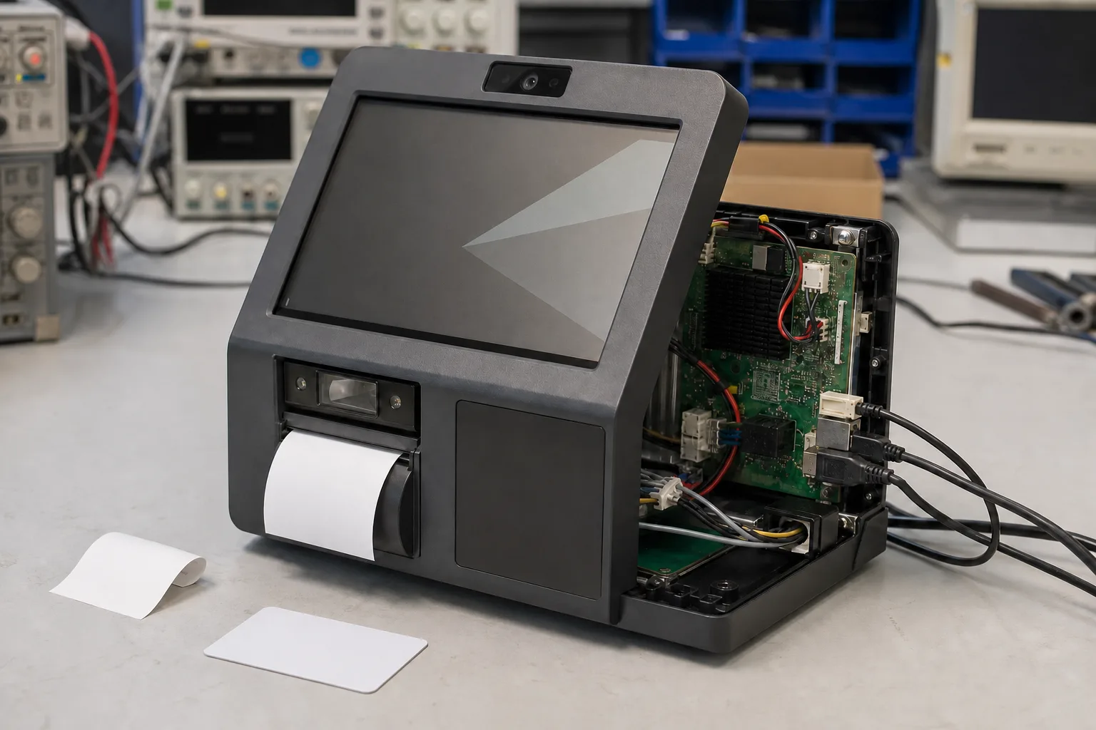
An Android smart terminal can look finished long before its hardware is ready for production. The app launches and each peripheral works alone. Then the printer, scanner illumination, and camera run together and the board resets. Or the NFC reader loses range after the metal bracket and display are installed.
These are system-integration failures, not isolated peripheral problems. An OEM smart terminal needs the scanner, camera, printer, NFC reader, Android image, power system, enclosure, and application to survive the same transaction at the same time. That is the standard this checklist uses.
Begin with the transaction, not the connector count
Write down one complete user flow before choosing hardware. A retail terminal might wake, identify a user by NFC, scan a product, capture an image, send data, and print a receipt. An access terminal may run face preview, read a credential, drive a relay, and store an event during a network outage.
The sequence shows which devices operate together, their response targets, and which failure stops the transaction. It also gives the factory a repeatable acceptance test.
For every peripheral, freeze the exact module, firmware, interface, cable, connector, and software package. “USB scanner” or “NFC module” is not a production specification.
| Peripheral | Decisions to freeze | Common late-stage surprise |
|---|---|---|
| Barcode scanner | USB HID, USB serial or UART; trigger; supported codes; SDK | Data arrives as keyboard input when the app needs status and trigger control |
| Camera | MIPI CSI or USB UVC; sensor; lens; focus; orientation; frame rate | Preview works, but exposure, rotation or suspend recovery does not |
| Thermal printer | UART or USB; voltage; paper width; cutter; sensors; command set | Peak current causes brownout or cutter errors |
| NFC reader | I2C, SPI, UART or USB; card technologies; antenna; firmware | Read distance changes after final plastics, display or metalwork |
Choose interfaces around control and recovery
USB can shorten development, but it is not automatically the best internal interface. A USB HID scanner enters decoded text with little application work, yet may offer limited control over illumination, trigger mode, errors, or firmware. A documented serial protocol can be more predictable when explicit command and response behavior is required.
The same trade-off appears with cameras. USB UVC is convenient and mechanically flexible. MIPI CSI may reduce module cost and USB loading, but ties the sensor, device tree, driver, camera provider, orientation, and tuning to the Android BSP. Samples must use the intended sensor and lens, not a temporary webcam.
Count the complete USB topology. Internal hubs, wireless modules, camera, scanner, printer, service port, and external ports may share a controller or power rail. Confirm cold-boot enumeration, suspend and resume, reconnect, and recovery after a peripheral stalls. The official Android USB host documentation explains application discovery and permissions; the product still depends on kernel support, hub design, and stable power.
An Android SBC shortlist should therefore be reviewed with the actual peripheral tree attached. A datasheet showing four USB ports does not prove that four high-demand devices will behave correctly together.
Budget for transient power, not average current
Idle current is a poor basis for power design. Printer heads and cutters are obvious peaks, but scanner illumination, camera startup, backlight, LTE transmission, and USB inrush can overlap. Thin cables and small connectors add voltage drop even when the adapter rating appears sufficient.
A useful first-pass budget separates continuous and transient demand:
continuous_budget = SBC_peak + display + active_peripherals + design_margin
transient_budget  = continuous_budget + printer_head_or_cutter + USB_inrush
Use measured values from the selected modules. Test with the final adapter, cable, harness, paper, and enclosure. Monitor the SBC input while printing dark patterns, starting camera preview, scanning, reading NFC, and transmitting data. A reset log alone cannot distinguish software failure from a short voltage dip.
If the printer uses another voltage, review grounding, return-current paths, protection, and sequencing. Do not route motor or head current through a logic-power connector. Battery designs also need peak testing at low charge and relevant low-temperature conditions.
Define the Android BSP and application boundary
Peripheral work crosses several layers. Procurement may receive the SDK, the board supplier may own kernel and Android image changes, and the customer may own the app. Without written ownership, every layer can pass separately while the transaction remains unreliable.
For each device, assign responsibility for:
- Kernel driver, device tree, pin control, and power enable.
- Android permissions, SELinux policy, HAL or system service where required.
- Vendor library or SDK version and source availability.
- Application API, timeout, retry, and user-facing error state.
- Firmware update method and compatibility record.
- Logs that identify disconnect, timeout, permission, or hardware failure.
The app should not assume a peripheral is always present. Define behavior for paper-out, cover-open, scanner timeout, camera unavailable, and NFC failure. Decide which fault permits continuation and which requires service instead of leaving recovery to an Android exception dialog.
Settle the app, BSP, and module responsibilities as part of the peripheral integration plan before freezing the enclosure and Android image.
Let the enclosure participate in the test
Peripheral placement is functional. A scanner window affects angle, reflection, and working distance. The camera needs the correct field of view through cover glass. A printer needs a straight paper path, accessible roll replacement, heat clearance, and a cutter opening that does not collect scraps.
NFC is especially sensitive to its surroundings. Keep the antenna area clear of unsuitable metal, route cables consistently, and validate with the final display, battery, bracket, plastics, paint, and adhesive. Mark the tap area only after real users have tested it. A reader that works at an electronics bench may feel unreliable when customers tap in different positions or with different card types.
Use keyed, serviceable internal connectors and strain relief. If a standard board forces long adapters, stacked hubs, or cables across the printer path, a custom SBC may reduce assembly time and field failures.
Build an acceptance test that follows real use
Do not approve samples after one successful scan, one photograph, one receipt, and one NFC read. Run the devices in the order and frequency expected in the product. Include these checks:
- Cold boot with every peripheral connected and confirm deterministic discovery.
- Repeat the complete transaction while network traffic and display brightness are high.
- Print dense patterns and operate the cutter while monitoring the input rail.
- Scan damaged, glossy, small, and low-contrast codes at realistic angles.
- Check camera preview, capture, focus, exposure, orientation, and long-run temperature.
- Read every required NFC card type through the finished enclosure.
- Suspend and wake the terminal, then repeat the transaction without rebooting.
- Disconnect and reconnect serviceable USB or serial devices in different orders.
- Remove paper, open the printer cover, block the scanner, and deny camera permission to verify useful error handling.
- Interrupt power during idle and active operation, then confirm application and peripheral recovery.
Production does not need every engineering stress case, but it does need known test media and unambiguous pass/fail evidence. Keep a reference barcode set, NFC cards, camera target, printer pattern, approved firmware versions, and a golden terminal. During smart terminal production testing, record the image version, app version, peripheral firmware, serial number, and result for each unit.
Control substitutions before pilot production
A matching connector does not make peripherals interchangeable. A replacement can change USB identifiers, UART protocol, commands, peak current, lens geometry, antenna behavior, SDK, or permissions. Even a cable revision can affect signal integrity or assembly strain.
Procurement should maintain an approved peripheral list with exact manufacturer part number, firmware, cable, connector, and validated Android image. Proposed alternatives should go through the same transaction, power, enclosure, sleep/wake, reconnect, and production tests before release. This discipline is usually cheaper than diagnosing mixed hardware after shipment.
What to send with an RFQ
For a useful recommendation, send the user flow, screen specification, exact peripheral models, interfaces, Android version, application ownership, power source, enclosure drawing, quantity, and certification direction. Include sample peripherals when possible; photos of cable exits and the printer mechanism answer questions a spreadsheet misses.
The strongest Android smart terminal design is not the one with the most interfaces. It is the one whose full transaction has been measured, recovered, assembled, and tested with controlled hardware. That is what turns a working demonstration into a repeatable OEM product.
Frequently Asked Questions
Is USB the best interface for every Android smart terminal peripheral?
No. USB is convenient for many scanners, cameras, and printers, but UART, MIPI CSI, I2C, or SPI may provide better control, lower cost, or a cleaner internal design. The choice depends on driver support, cable length, power, reconnect behavior, and enclosure layout.
Why can a thermal printer reset an Android terminal?
The printer head and cutter can create a short, high current demand. If the adapter, DC input, regulator, wiring, or bulk capacitance is undersized, the voltage can dip and reset the SBC or disconnect USB devices. Peak operation must be tested, not estimated from idle current.
Can the camera or scanner model be changed after the Android BSP is finished?
A substitution may require driver, SDK, permission, image, mechanical, and application revalidation. Procurement should use approved exact models and treat untested replacements as engineering changes.
What should be included in smart terminal peripheral production testing?
Testing should use known barcodes, NFC cards, camera targets, and printer patterns. It should also verify cold boot, sleep and wake, reconnect, repeated transactions, software versions, serial number, and recovery after interrupted power.